The unexpected reaction of CATV antenna manufacturers to the new DTV reception requirements brings back the memory of a very, very old German joke.
Radio
announcement: “Achtung, Achtung,
there is a wrong-way driver on the Autobahn!”
Says the old man: “One? There are
thousands!”
With the introduction of Digital TV the over-the-air TV reception landscape changed dramatically. Unfortunately, none of the CATV antenna suppliers reacted positively.
These days practically no DTV station operates in the Low-Band, and fewer than 10% of the TV stations broadcast on High Band. However, the most dramatic change occurred on UHF, where the top 110 MHz of the original 470 to 800 MHz frequency range was eliminated. It was auctioned for $20 Billion to cell phone and mobile Radio companies.
When you squeeze 90% of the DTV stations into the more narrow 310 MHz-wide spectrum, you are looking for trouble.
Were these changes justified and well advised? It’s now water under the bridge.
We in the Cable TV industry expected that antenna manufacturers would respond accordingly, taking advantage of the new, limited bandwidth, and retune their popular wide-band parabolic antennas to the actual 470 to 690 MHz frequency range.
Has WADE ANTENNA taken the opportunity to redesign its six foot parabolic, the Model PB 61-BB, for the new, reduced bandwidth, in order to deliver more antenna gain, better directivity in the highest and lowest UHF channels where the radiation patterns got distorted and the antenna gain was reduced?

Well, nothing happened, except that the six foot parabolic was promoted to digital antenna, but still advertized as a Channel 14 to Channel 69 parabolic in the WADE catalog! The signal collector, located in the parabolic’s focal point, was not retuned to improve performance!
In the 1987 movie “Wall Street”, Gordon Gekko declared: The point is, ladies and gentleman, that greed, for lack of a better word, is good. Apparently, the antenna manufacturer has been motivated entirely by profit, unhindered by a sense of responsibility for the greater good of quality HDTV reception.
Surveying West Coast CATV antenna systems, the Scala/Kathrein Paraflector was identified as the most popular UHF antenna.

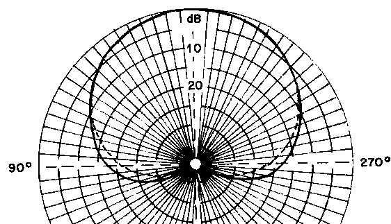
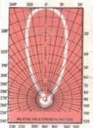
While the cut-parabolic’s reflector screen creates high compression in the vertical, directivity in the horizontal plane is limited to the dipole/reflector combination. A vertical reflector cannot produce directivity in the horizontal plane! The E-plane (Azimuth) radiation pattern, as published in the Scala catalog, as shown on the left, has nothing to do with reality. It was created on a drawing board, not on the company operated antenna test-range.
 |
 |
Displayed in the Scala catalog |
More realistic pattern conditions are shown on the right-side, emphasizing the Paraflector’s extremely wide, almost circular pattern in the horizontal plane, where directivity is at premium. In metropolitan areas, where ghosting is a major concern, the application of the Scala cut-parabolic is not recommended.
Observe the 470 to 862 MHz specification above the Paraflector picture, creating the impression that this is a wide-band UHF antenna, which it’s not. This is a single channel antenna. When ordering this model, the identification of the desired channel is mandatory. The catalogue’s 470 to 862 MHz specification resulted in a number of multi channel applications -- with disappointing results.
A
desire to enter the

The ZIG-ZAG has reasonable antenna-gain and Front/Back ratio specifications. But their sales brochure includes claims that “it offers the best solution against ghosting, noise and co-channel interference” - a less-than-modest statement, which may open a large can of worms.
The 8-bay, vertically stacked traveling wave type transmission line structure, assisted by a grid-type flat reflector screen, exhibits high directivity in the vertical plain, but very limited directivity in the horizontal (E-plane). Since interference signals, such as second harmonics of FM stations, co-channel and adjacent channel or AC interference arrive by the sideways, the single bay Zigzag should be limited to the reception of local stations.
Also, the long transmission line, forming the eight-bay radiator, can expose the antenna to corrosion problems, resulting in less than perfect picture quality and diminishing interference protection as the antenna ages.
Significant interference protection improvements were achieved by developing the two-bay, horizontally stacked Zig-Zag array, as displayed below. The properly calculated horizontal spacing can force a deep radiation pattern null into the direction of the interference source.

Positioning Zigzag antennas back to back at the same elevation on the tower is strongly discouraged. The mutual coupling between closely spaced antenna-arrays can significantly reduce antenna-gain, also steering otherwise properly calculated radiation pattern nulls into undesired directions.

The photograph above demonstrates that the antenna supplier’s technical staff was not experienced in antenna system design. The back-to-back installation of ZIG-ZAG antennas is ill advised, violating basic CATV antenna engineering standards.
Observe Lindsay’s published radiation patterns (displayed below) for single, two-bay and four-bay horizontally stacked ZIG-ZAG arrays. The usual story: They came from drawing boards, not the results of carefully conducted antenna test-range measurements. These quasi-ideal radiation patterns, free of side and back-lobes, could not be confirmed by real-life testing.
 |
 |
 |
Single SZZ |
2-Bay SZZ |
Quad SZZ |
AN INESCAPABLE CONCLUSION
The bottom line: DTV reception technique, antenna-tower/antenna–array design is not the slam-dunk that antenna manufacturers or their service partners would have you believe.
You owe it to your customers (and your own peace of mind) to enlist the opinion of an independent third party, not committed to any supplier, or line of antennas.