THE BIRO TECHNICAL BULLETINS
JANUARY 2002
AWACS AIRPLANES:
SATELLITE RECEPTION'S CLEAR AND PRESENT DANGER...
Entering
the post September 11 era of 2001, many American cable systems experienced mysterious,
very annoying pulse-type interference on certain satellite pictures.
Digital satellite transmissions may suffer complete fade-outs.
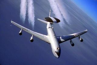
Meet
AWACS, which is an acronym for the military's Airborne Warning
and Control System. It operates special airplanes, patrolling up
and down the coast of the United States, focusing on major metropolitan areas.
These
airplanes fly 20 to 30,000 feet above ground and operate powerful Pulse Doppler
radars with very narrow (short) pulse-width.
The 10 GHz radar antenna scans mechanically the terrain at six revolutions
per minute (10 seconds/revolution).
The AWACS
radar transmitter, using powerful interleaving and de-interleaving algorithms,
is the source of interference. The spurious
beats fall more often than not outside the 3.7 to 4.2 GHz C-Band spectrum, although
occasionally they appear within the desired frequency range,
It is
not an industry secret that a high-quality, 3.7 to 4.2 GHz bandpass filter,
installed between the parabolic's feedhorn and the LNB should provide the necessary
filtering. But how about those large
pulses falling within the 3.7 to 4.2 GHz band? Unfortunately, a bandpass filter provides no
protection against in-band spurious signals.
The
US AIR FORCE planes carry 30 feet diameter and six feet thick rotating radar
domes. The radar has a range of more
than 250 miles. The radar created interference
has a range of more than 400 miles.
Returning
to CATV system conditions on the ground, the photograph below shows the downconverted
950 to 1450 MHz Galaxy 5 spectrum, with the analyzer operating in the 100 MHz/Div
horizontal scan and 10 dB/Division vertical deflection mode. Observe the noise floor (bandwidth) of the
LNB. It is much wider than the 500 MHz
designated to C-Band.

A one-stage
filter guarantees the lowest insertion
loss, probably in the 1 to 2 dB range, but its skirt selectivity is very shallow.
On the other hand, the selectivity of a multi-stage bandpass filter would
be quite acceptable, but at a price of high insertion loss.
A low-loss
bandpass filter, inserted into the front of the LNB would reduce the Carrier/Noise
ratio by 1.5 to 2 dB. In satellite reception
even 1 dB reduction is undesirable.
To compensate
for this Carrier/Noise ratio reduction, re-orient the antenna in the horizontal
and vertical plane, increasing the desired carrier level. Then, turn your attention to the issue of polarization
isolation, eliminating or reducing the crosspolarized transponder carriers from
the spectrum. Improvement in crosspolarization
isolation will boost the amplitude of the desired transponder carriers, improving
the Carrier/Noise ratio, as well as reducing the noise in the adjacent channel.

The above
GALAXY 5 spectrum, photographed in one of the New York state systems, shows
a spectrum with exceptional high polarization isolation.
Turning
our attention to a situation when the interference falls into the 3.7 to 4.2
GHz frequency range, reception conditions may become critical, but not hopeless.
As a
matter of fact, when the desired satellite signals arrive from an elevation
angle 15° or higher, the
system should not experience any AWACS radar interference. Follow this brief analysis:
Airplanes,
flying at 75 miles and circling at 25,000 feet, appear to the observer on the
ground just about one or two degrees above the horizon. From flights at 150 miles or further, the radar
signals arrive just a tiny bit above the horizon, practically 0 degree elevation
angle. Shouldn't a high quality 3 to
5 meter diameter parabolic antenna, exhibiting a narrow main beam, provide 40
to 50 dB protection 15 to 20 degrees off-the-main beam? If the antenna is still
receiving radar interference, it is a strong indication that the advertised
perfect radiation pattern is less than perfect.
(See picture below).


Microwaves, arriving at 0° elevation angle, cannot penetrate earth or high density vegetation. The height and position of this artificial barrier in front of the parabolic is critical and should be carefully calculated. No room for mistakes!

In October NATO AWACS have taken over the aerial surveillance, replacing the American aircrafts, which were transferred to the Afghan theater. NATO interference intensities are matching those of the US Air Force radars.
For emergency engineering services:
Call: (609) 883-9866
E-mail: steven@biroengineering.com
Web site: www.biroengineering.com
Biro Engineering
P.O.BOX 2175
PRINCETON, N.J. 08543