On November 1, 1999 we passed a significant milestone in our calendar. On that day the top 30 market's TV stations had to be on the air with digital signals, reaching nearly 75% of the nation-wide TV audience. With more than 80 DTV stations in operation, delivering 95% of the regular and made-for-HDTV programs, the responsibility shifted to Cable TV systems, serving 70% of the TV audience, for the full benefits of crystal-clear, high-resolution pictures and first-quality digital sound.
INTERFERENCE EFFECTS HAVE BEEN REPORTED IN THE LOS ANGELES AND BALTIMORE METROPOLITAN AREAS, ALTHOUGH ONLY THE MAJOR NETWORKS OPERATE DTV STATIONS, OFTEN AT REDUCED POWER.
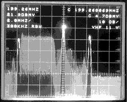
During the 1999 to 2006 transition period the off-air TV spectrum will become more and more crowded with broadcasters operating analog and digital transmitters from the same tower. Adjacent channel interference will be the rule, not the exception, as demonstrated below.
Observe distant New York high-band reception conditions in Danbury,
Ct. The Channel 10 DTV transmitter of New Haven, simultaneously operating
with the Channel 8 analog station, caused strong adjacent channel interference
for the reception of Channel 9 and Channel 11, New York.
The reception of DTV signals requires a long processing chain.
The performance of the entire chain cannot be better than its weakest link,
which might be the receiving antenna. Should the antenna deliver
insufficient signal levels, exhibiting impedance mismatch or less than
adequate protection against ghosting, the cherished HDTV video will not
look much better than the good old NTSC analog pictures.
In field tests, conducted by a major broadcaster, multipath (ghosting), was found lethal to HDTV reception. The perfect cure: the installation of a "pencil-beam" antenna. Unfortunately, in the real wold of TV and CATV, antenna radiation patterns are affected by backlobes and sidelobes, while the width of the main lobe is much-much greater than the "pencil beam".
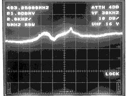
In Part I of evaluating antennas for HDTV reception, a popular UHF rooftop antenna, promising 200 mile VHF and 80 mile UHF reception range, was tested for impedance match. The findings were not very encouraging. This time radiation pattern tests were conducted for the same model. The Polaroid pictures below show the test-results on Channel 16 (483.25 MHz) and Channel 33 (585.25 MHz) furthermore Channel 48 (687.25 MHz) on the next page.
The instrumentation was operated in the 10 dB/Division vertical deflection
and 36° rotation/division horizontal scan mode, presenting a 360°,
full circle radiation pattern. The rectangu-lar radiation pattern
presentation enhances the easy and precise determination of the Front/Back
ratio, as well as the beamwidth of the unit.
 |
 |
| The radiation pattern on Channel 16, the low end of the UHF Band, was found quasi omnidirectional. No well defined main-lobe, ex-tremely wide side and back lobes. | The performance on Channel 33, in the mid UHF range, was much improved, but less than satisfactory efficient ghost rejection. The Front/Back ratio was only 8 dB. |

On Channel 48, in the upper range of the UHF band, the radiation pattern was anything but desirable. The Front/Back ratio was found practically in the 0 dB class.
The tested rooftop-type broadband UHF antenna should not be used for the reception of HDTV programs.
BACK TO THE MAIN EVENT.
TESTING A MADE-FOR-CATV ANTENNA

Special attention was paid to the forward performance of this 12 element
Yagi, recording the -60° to +60° sector of the radiation pattern
in greater detail. The instrument was operated in the 10 dB/Division
vertical deflection and 12 degree/division horizontal scan mode.
| Test results: | 34° beamwidth, with a well defined main lobe.
First deep nulls at 36° on each side of the main lobe. 13 to 17 dB down symmetrical sidelobes. 20 dB Front/Back ratio. |
THE BIRO COMPUTER RUNS
100 TIMES FASTER, 10 TIMES MORE
AND LISTING NEW DIGITAL TV STATIONS.
Biro Engineering offers not only the customary Computer Aided TV Reception and Co-Channel Interference Studies, but the proprietary Computer Developed Co-Channel Signal Direction Sheets for every desired VHF and UHF channel, with 10 times more information than provided by the average antenna manufacturer, offering path-loss analysis. (Who needs path-loss analysis when you have interference problems?)
We deliver this service via the Internet, sending information to your desktop in minutes, not in days or weeks. Or, if you prefer a more traditional information transfer, the FEDEX delivered package could be on your desk the following morning.
After receiving the information package you may still have questions.
Please, give us a call. You will find an experienced engineer on
the line, who will be happy to discuss your site selection con-cerns, electrical
and co-channel interference or ghosting difficulties.
| Biro Engineering | ||
| Tel: (609) 883-9866 | Fax: (609) 883-2702 | Email: sales@biroengineering.com |